THz Sources and Detectors
Two distinct methods exist to generate and detect THz radiation using ultrafast laser systems. In the Schmuttenmaer group we utilize two different techniques: photoconductive antennas and non-linear optics. The mechanisms for terahertz generation and detection using those two techniques are described below.
Photoconductive Antennas
Generation
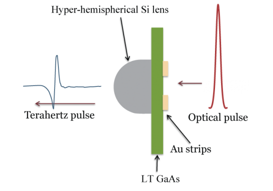
A typical photoconductive emitter consists of a semi-insulating gallium arsenide (GaAs) chip with two microscopic gold transmission lines ~ 30 μm apart. A bias voltage is applied across the chip via a square wave generator at ~30 kHz. A mode-locked Ti:Sapphire laser generates ultrafast (100 fs or shorter) optical pulses at 800 nm with a repetition rate of 80 MHz. These pulses are focused between the two gold transmission lines, rapidly populating the GaAs conduction band. The excited electrons are accelerated by the bias, which creates a transient current. The transient electric field emits a linearly polarized radiative pulse front with spectral components centered in the THz frequency range. The semiconductor recovers after hundreds of picoseconds. This effect is explained by Maxwell’s equations: the transient electric field is proportional to the time derivative of the photocurrent. In order to obtain a larger bandwidth of THz frequencies, a shorter excitation pulse is needed to create a much faster rising photocurrent, thereby creating a THz pulse over a smaller time interval.
Detection
Terahertz detection follows is accomplished by using another photoconductive antenna. In this case, the electric field of the incoming THz pulse provides the bias. If both the THz and optical pulses arrive simultaneously, the optical pulse excites electrons and the electric field of the THz pulse accelerates these electrons. By varying the arrival time of the optical pulse with respect to the THz pulse (using a delay line), the electric field intensity of the THz beam can be mapped as a function of time.
Non-linear Optics
THz radiation can also be generated and detected using crystals with large second-order non-linear susceptibilities. Either ZnTe or GaP is the typical crystal of choice due to minimal velocity mismatch between the THz pulse and the optical pulse which generates it.
Optical Rectification
The polarization P of a material induced by an electric field (such as the electric field of a pulse of light) is related to the applied electric field E and the electric susceptibility of the material Χ(E) by the following equation.
P = χ (E)E
To account for nonlinearities, the susceptibility can be expanded according to the equation below.
P = (χ1 + χ2E + χ3E2 + …) E
Optical rectification is a second order non-linear optical effect described by the χ2 term in the equation above. Substituting E = E0cos(ωt) to account for the time-varying intensity of the electric field of light gives the following equation, where P2 represents only the second-order contributions to the polarization.
P2 = χ2E1E2 = E1cos(ω1t) x E2cos(ω2t) = ½E1E2 {cos[(ω1 + ω2)t] + cos[(ω1 - ω2)t}
After applying a basic trigonometric identity, the equation contains both sum and difference frequency terms. Optical rectification is a result of the difference frequency term.
Free-space Electro-optic Sampling
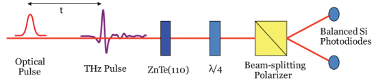
When the THz pulse is impingent on the crystal, its electric field causes a change in the refractive index of the crystal, and this birefringence is proportional to the THz electric field (the Pockels effect). If an optical beam passes through the crystal at the same time as the THz pulse, its ellipticity will be altered by an amount proportional to the THz electric field. By changing the delay time between the THz pulse and the optical pulse, the THz electric field is determined as a function of time.
Related Publications
Harrel, S. M., R. L. Milot, J. M. Schleicher, and C. A. Schmuttenmaer , Influence of free-carrier absorption on terahertz generation from ZnTe(110) , J. Appl. Phys. , 2010 , 107